

|
|
|
|

All photos ! |
As mentioned before this robot was developed in the context of the RoboVision 2000 competition. Function of this robot was to drive through a orthogonal maze. After that it should bring 4 balls from 4 bases. We decided to shot this 4 balls of these bases. Important was here that the Vision Command called Lego Camera had to be used. In order to be able to always see in the same direction with the Camera (and the IR communication) we decided to build a Synchrodrive. Unfortunately we did not have Lego turntables, that's why we had to build turntables ourselves. |

All photos ! |
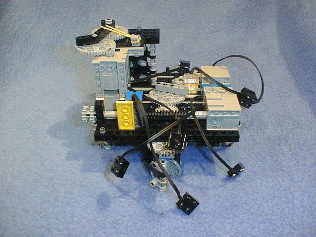
Our selfmade turntables permits approx. 100° of freedom. With other levers between wheel-set and main-wheel larger turns are possible. Since Lego always has a little inaccuracy (and must have) the use of other levers brings then however a disadvantage for the accuracy of the steering element. Beside a RCX two turning sensors and four engines were used. The turning sensor monitors the adjustment of the wheels, the other one the turn of the wheels. 2 engines drive the wheels (it could actually be done with one, because the wheels always turn into one direction), 1 engine steered the wheels, the last engine activateed our rocket launcher. |
All photos ! |
In this photo you can see the rocket launcher in use. Unfortunately they only gave us three of these catapult-sets. |
All photos ! |
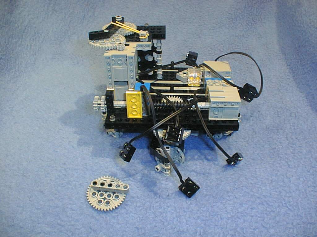
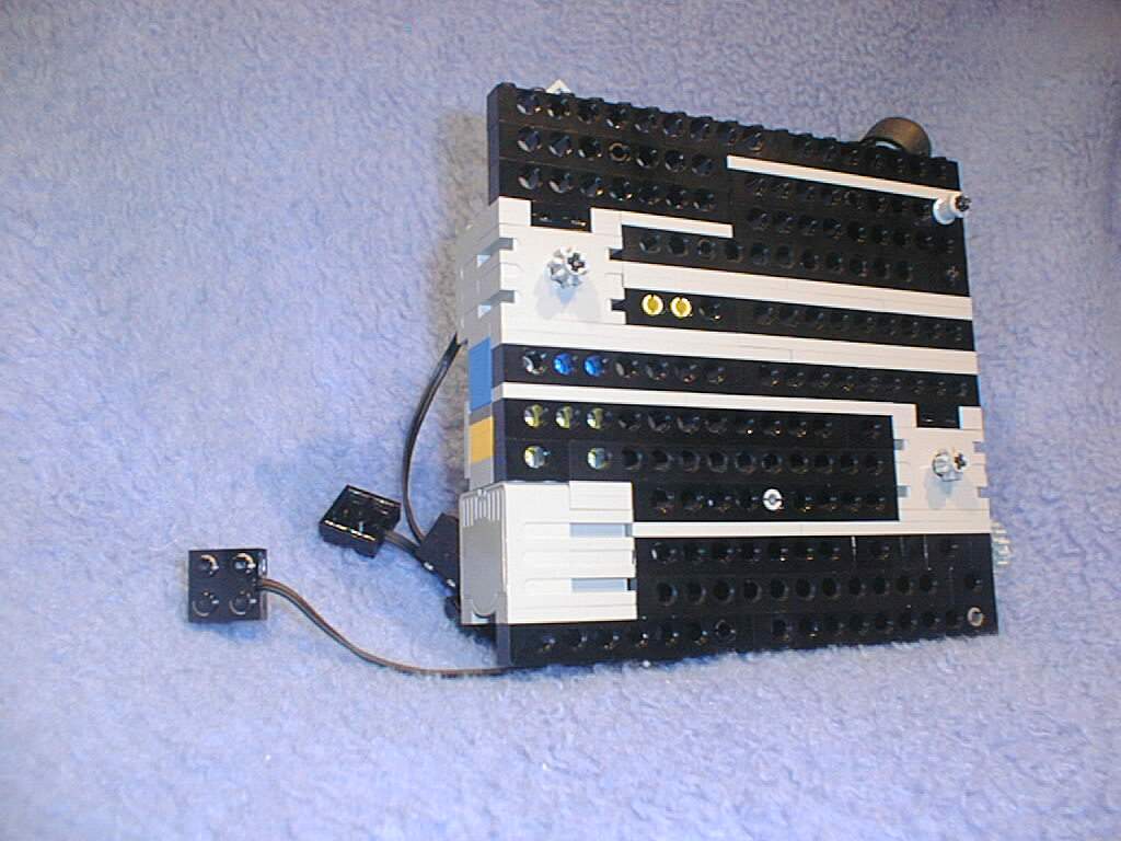
That's what the robot looks without the RCX. In the foreground you can see the worm drive, which is responsible for the adjustment of the wheels. On the same axle is also the turning sensor, which monitors the turn. The two gear wheels quite left on the axle serve as handwheel. The engines on the left (down) and on the right (in the back) are the driving motors of the wheels. The other engine left (above) operates the rocket launcher. The middle gear wheel transfers the turn downward. On the gear wheel is a mechanical limiter, which is to prevent, that the wheels turn over like a spring-actuated lock. |
All photos ! |
The Clou: If take off the middle gear wheel, you can separate the base from the chassis. |
All photos ! |
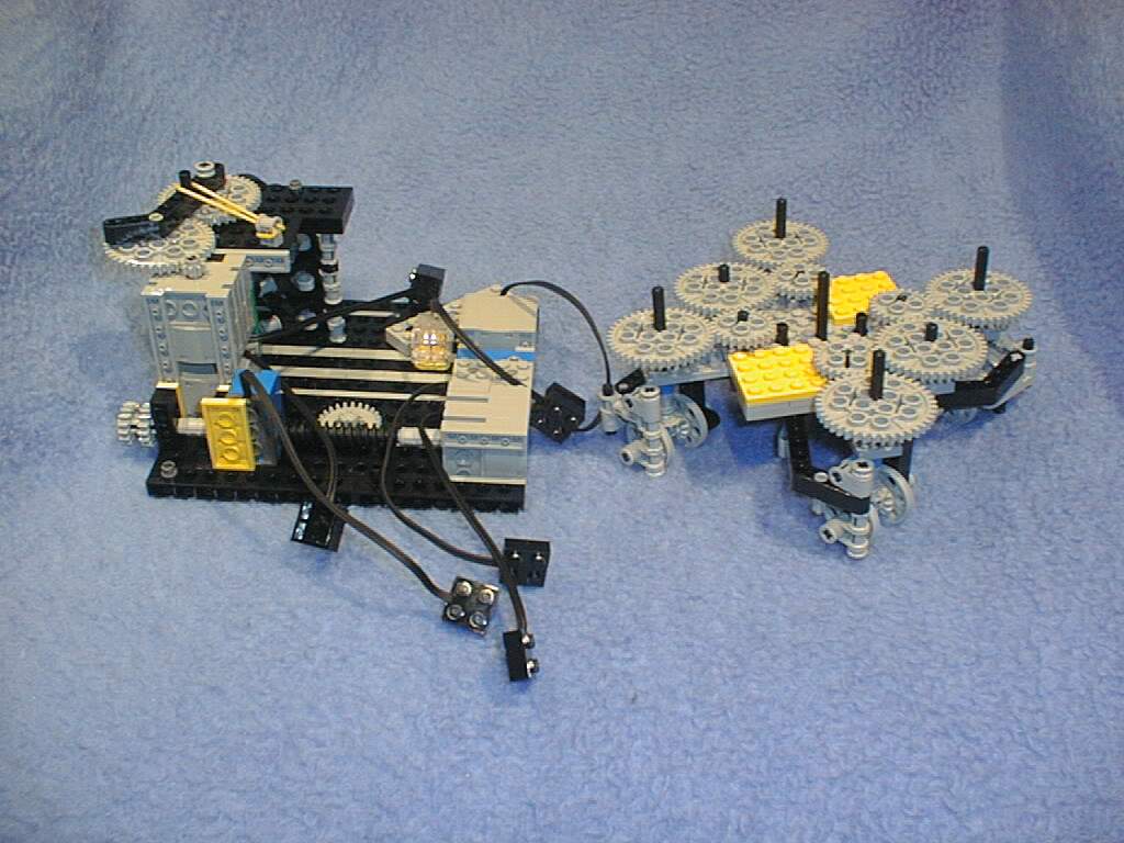
Thus the base can be build freely up to few restrictions. The restrictions are:
1. The holes for the axles must be available 2. The engines for the drivemust be at the same place 3. The axle for the adjustment of the wheels must be attainable |
All photos ! |
Thus the base we build looks from downside. The base is smooth apart from the two gear wheels of the wheel drive. |
All photos ! |
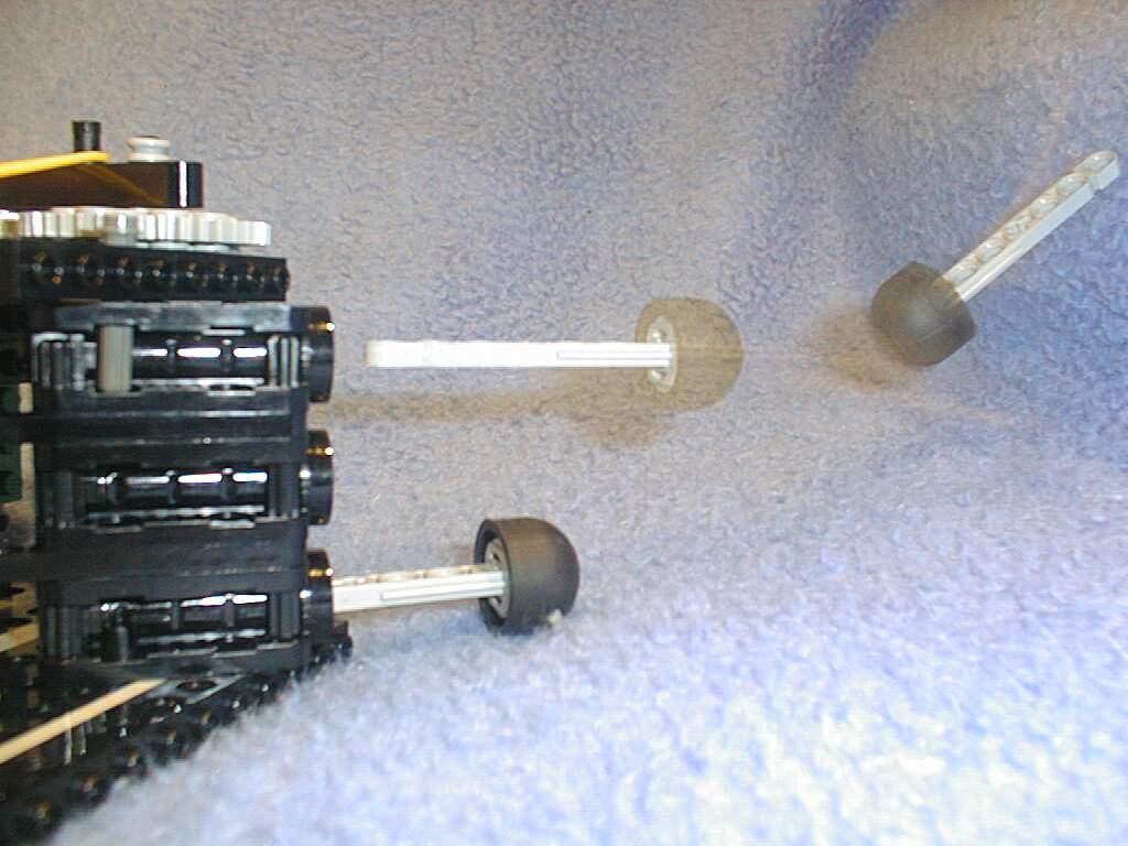
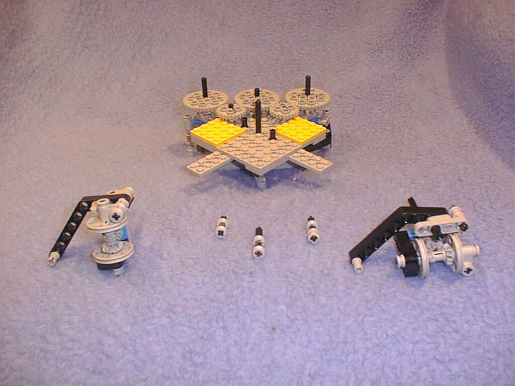
The two different wheel sets in front of partial dismantled chassis. There are two different wheel sets, because 4 equal wheel sets could never point to the same direction. The disassembly is held step by step in the photo page. |
All photos ! |
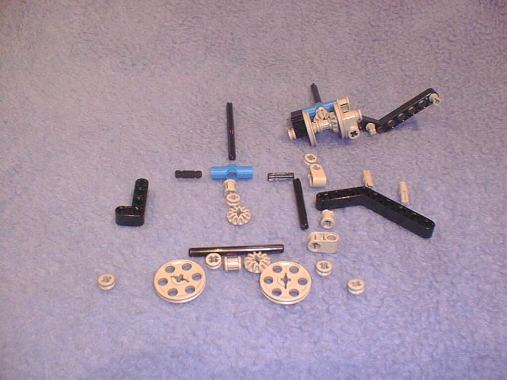
The simpler of the two wheel sets in the detail. Above on the right the assembled wheel set, left under it all necessary sections, placed that way that you can notice it position. NOTE! The red encircled section was changed by us. Normally one hole is for swivelling axles, the other hole for not swivelling axles. We needed however here a section, which permitted a swivelling axle in both holes. Therefore we out-filed locking for the cross axle with a little file. |
All photos ! |
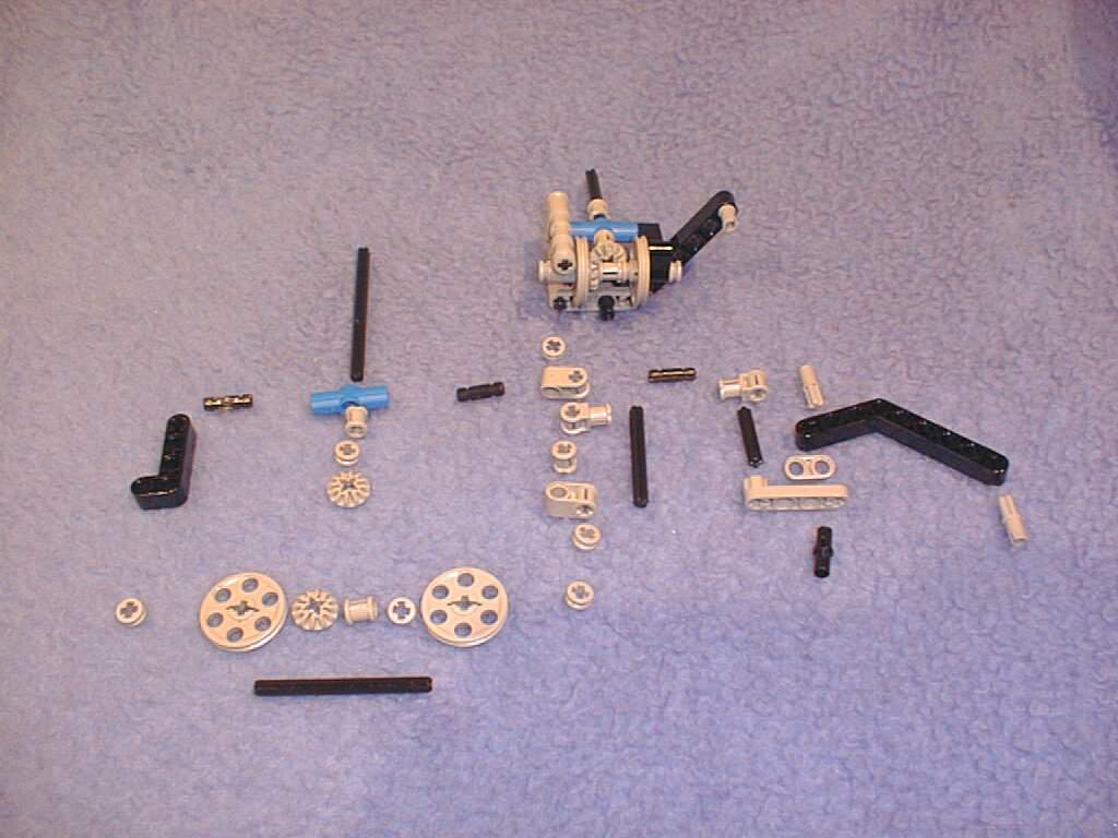
The difficultier of the two wheel sets in the detail. Above on the right the assembled wheel set, left under it all necessary sections, placed that way that you can notice it position. NOTE! The red encircled section was changed by us. This sections are available from Lego only in other sizes. We took one with five holes and made two with two holes out of it. |